The following parameter groups
•Geometry •Diffusion •Pre-Equilibrium •Level of Multi-Core CPU Support •Simulation Name
as well as the Simulation Parameters headlined
•Experimental Conditions •Model Parameters •2D-Simulation •FEM-Simulation work exactly in the same way as already described for cyclic voltammetry.
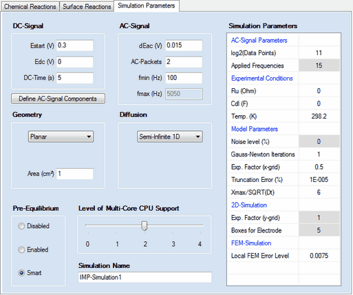
1. DC - Signal
•Estart (V), Edc (V), DC-Time (s)
The simulation is executed for an experiment conducted in the following way: at the beginning of the experiment the potential of the electrode is assumed to be at Estart (V) so that the initial concentrations are in agreement with the Pre-Equilibrium setting computed for this potential. Then the electrode potential jumps to Edc (V) and remains at this value for the time indicated by DC-Time (s) before the AC-Signal is superimposed. 2. AC-Signal Parameters
•log2(Data Points)
The number of data points used for generating the AC-signal. It must be an integer power of 2 and is 2^11 = 2048 by default. •Applied Frequencies
Number of frequency components from which the multi-sine AC-signal is generated.
3. AC - Signal
•dEac (V), AC-Packets, fmin (Hz), fmax (Hz)
The AC-Signal can be composed of up to 15 frequencies components which can be edited/defined by clicking on the button Define AC-Signal Components
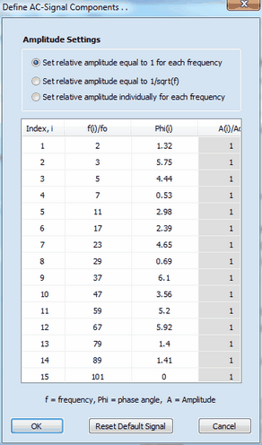
The AC-signal can be composed of up to 15 frequency components defined by frequency, fi, phase angle, φi, and amplitude, Ai. The values for frequency and amplitude are relative values referring to the basic frequency, fo (i.e. the frequency which would be obtained if the signal formed by the 2n data points (where n is the number defined in log2(Data Points)) covers exactly a single sinus cycle.) The overall AC-Signal is generated using the number of frequency components defined in Applied Frequencies. Then the amplitude of the overall signal is adjusted such as to mach the value defined in dEac (V) and the time regime of the simulation is adjusted in such a way that the lowest frequency component is equal to fmin (Hz). The "real world" value of the highest frequency component, fmax (Hz), depends on the number of Applied Frequencies and the value entered for fmin (Hz). The overall AC-Signal is cyclically applied n-times where n is the number defined in AC-Packets. Consequently, AC-Packets = 2 means that the overall signal is applied twice in the course of the simulation while the Fourier-Transformation is always executed for the last of the applied AC-Packets.
The simulation starts with computing the concentration profiles referring to the potential Edc (V) at the end of DC-Time. Then the simulation of the concentration profiles is continued taking also the superimposed AC-Signal into consideration. At the end of the simulation the current computed for the last AC-Packet and the applied electrode potential are analyzed by Fourier transformation. In the last step, the real and imaginary part of the impedance for each frequency component is computed from these data. |

